
Last year, I replaced all eight drives in my NAS with larger drives. However, I saved the old drives with the thinking that I could eventually upgrade from an 8-bay NAS to something with more bays. A 24-bay Supermicro device was the original plan, but I recently remembered that the 14-bay Xserve RAID is gorgeous. Unfortunately, the Xserve RAID was discontinued in 2008 and, barring the Xeon Xserve (non-RAID) models, never supported modern SATA drives.
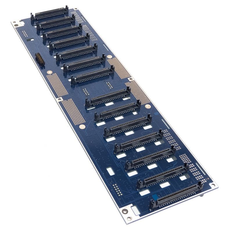
This is the first in what will likely be a series of posts regarding my attempt to convert an Xserve RAID (hereinafter "XR") to a modern storage device. To date, I have ordered an XR midplane (pictured above, basically a backplane to which drive caddies connect) and two empty (but not "blank") drive caddies. I have also explored a handful of SATA backplanes, though the backplanes I have found so far do not have the correct drive spacing (≈30mm from the start of one SCSI-esque(?) connector to the start of another). No matter, I have a couple other ideas for how to handle upgrading the XR from Ultra ATA to SATA.
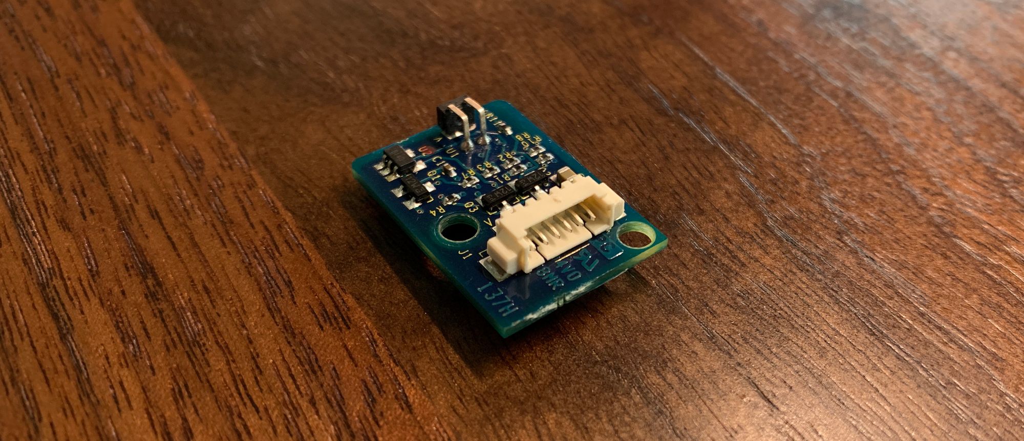
Which brings me to the topic of this post: the indicator lights in the drive caddies. Even though I would ultimately like all of the LEDs on the front of the XR to work, it makes sense to start with the drive caddies and, more specifically, the tiny PCB used by each drive caddy. Interestingly, there was a related project four years ago that seemingly never came to fruition.
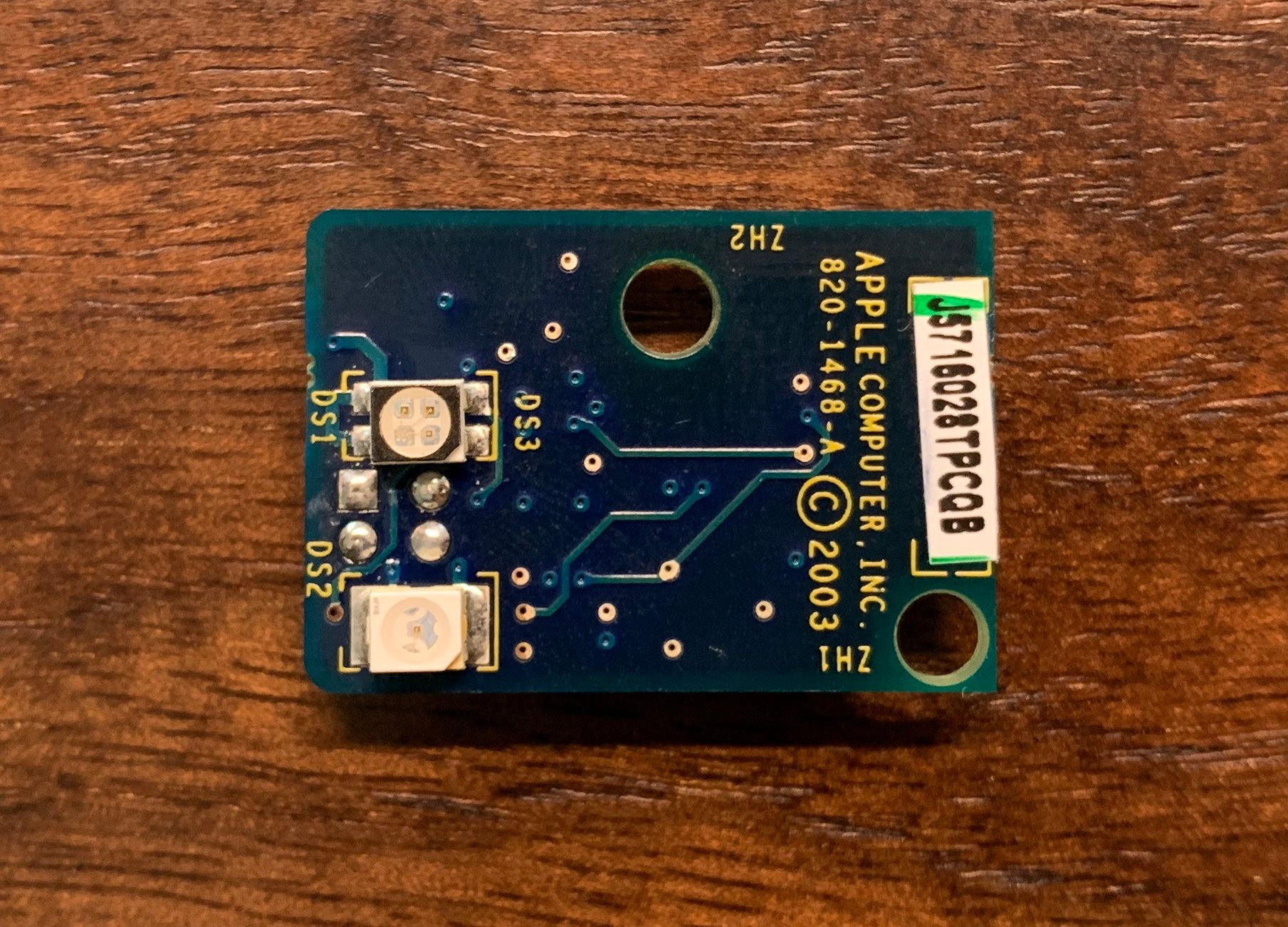
The top LED is the status indicator and can be green or red, while the bottom LED is the drive activity indicator is a pleasant shade of blue. Flipping the board over (below), the notable features are the 6-pin connector (right) and the reflectivity (?) sensor (left, with the two thick horizontal pins). The sensor is interesting, because, using white or black regions on the inside of the caddy, it detects whether the caddy is open / unlocked (e.g., for drive removal) or closed / locked.
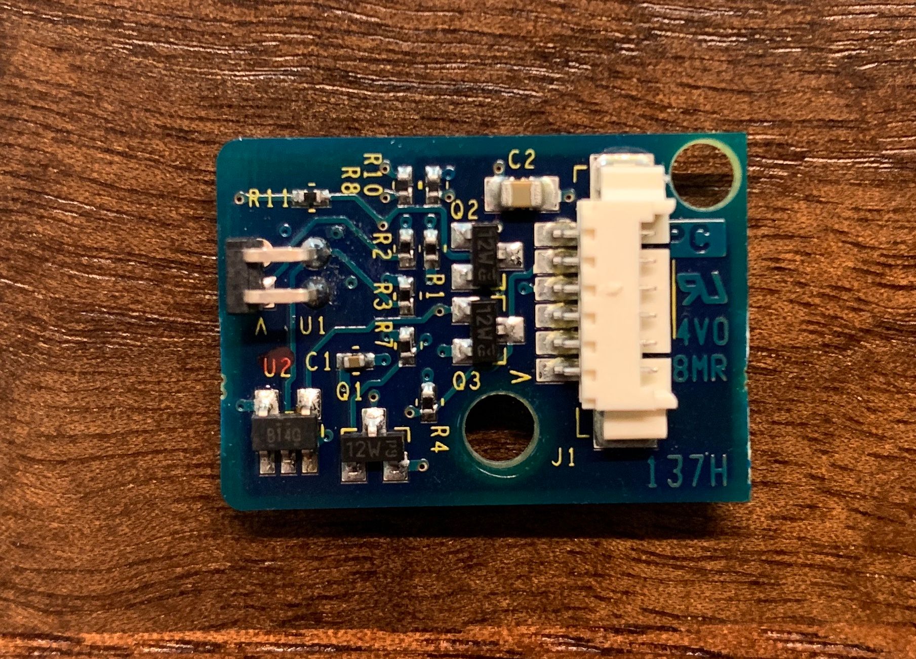
A thin, tiny cable plugs into the 6-pin connector and runs under the drive area to a PCB in the back of the caddy, where the traces ultimately lead to the connector for the caddy (which is what plugs into the midplane). The connector is interesting, because the ultimate goal is to connect the baby PCB to SATA power and activity leads so the lights on the front of the caddy behave as expected.
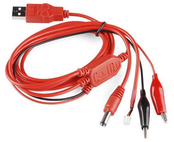
Using the above cable, I was able to easily supply +5V/GND to various pins of the PCB. The "V" and associated red coloring on the cable that connects to the PCB (not pictured 🤷🏻♂️) was a good indicator of where the positive pin is, but the rest required some guesswork. One fried sensor later, below is the pinout:
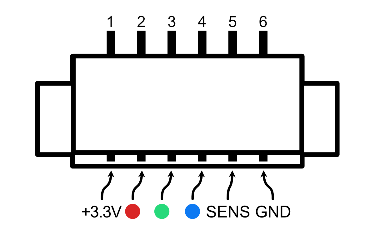
A quick edit regarding the voltage: after some additional testing at 5V, parts of the board became extremely hot (but it didn't let the smoke out). Upon further review of the SCSI connector, it appears SCSI operated at 15V and 3.3V, rather than the 12V and 5V typically used by SATA. So I think 3.3V is a safe bet.
I am guessing on the pin marked "SENS," but it isn't a pin that I need anyway. I am also unsure whether I'm conforming to normal pinout conventions, so I will write out the various states, too.
In order to produce a red color on the status indicator, +3.3V is applied to pins 1 and 2, with GND on pin 6. However, I don't anticipate using that state (as much as I would like to, I just don't see how it would be easily implemented). In order to produce a green color on the status indicator, +3.3V is applied to pins 1 and 3, with GND on pin 6. Finally, the activity LED can be illuminated by supplying +3.3V to pin 4 and, unsurprisingly, GND to pin 6. I may play around with supplying lower voltage on pins 1, 2, or 3; I haven't decided yet.
So, my plan will be to find a backplane PCB with activity and power leads / LEDs, so I can wire pins 1, 3, and 6 for power (i.e., yielding a green color on the status LED of the caddy) and pin 4 (and pin 6) for disk activity.
Edit 2021.06.14: After further experimentation, this post has been updated to reflect a voltage of 3.3V, not 5V.